You design the circuit... You can decide exactly how many microseconds of power you'll get between the brownout interrupt occurring and the lowest operating voltage. Your job as designer is to write the code to guarantee completion in that time.
Microcontrollers don't have to suffer the same issues as app/web developers. They can know exactly how many clock cycles something will take.
(a) you don't choose how long you get because the uC manufacturer already chose. (An external brownout warning is different, and useful, but still not a good solution to the problem of FS integrity.)
(b) those thresholds have nothing to do with the operating thresholds of the flash (which usually require a lot more energy to do work than the uC)
(c) writing to flash is a relatively high-power operation, and if you need to erase, you're doing the highest-power operation at a time when you have no power buffer
(d) warmup time to do an erase is measured in milliseconds, and you probably don't have that much power buffer
The best you can do at brownout is minimize the damage, because your uC is about to switch off and/or silently inject errors.
I don't personally usually bother, but an EE approach would be to put a diode between the 3.3V supply and the MCU/flash power supply pins with a large bulk capacitor, and use the voltage just before the diode as your brownout detection. It can't discharge back into the power supply or other parts on the board because of the diode so the capacitor just needs to store enough charge to run for a specified time after power loss.
Then you can configure how long the MCU runs after power shuts down. Put 470uF there and I imagine you'd have your milliseconds easily.
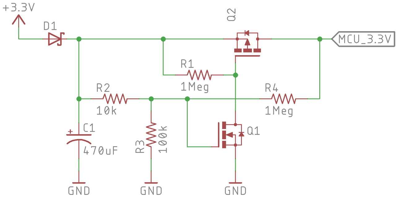
Another reply mentioned that many MCUs don't like it when power is applied too slowly. Here is a version I just made as an example that uses two MOSFETs and a resistor divider to delay application of power to the MCU and flash memory. It relies on the N-channel MOSFET turn on voltage along with the resistor divider to set the turn on voltage, and when it reaches the threshold the P-channel MOSFET turns on.
Note the resistor R4 provides hysteresis -- after the P-channel MOSFET activates it acts to keep the N-channel MOSFET active unless the voltage drops below some level set by R2, R3, R4, and the turn on voltage of Q1. You just need to tune them appropriate for your components, and granted of course it adds some amount a bit to your BOM cost. But if you need it you need it.
So basically, R2/R3/Q1 set your turn on voltage (experimentally determined or maybe with Spice) and R4 sets your turn off voltage with R2/R3/Q1. The MCU probably uses under 500mA so these parts are pretty cheap... the capacitor is about 5 cents (https://www.digikey.com/product-detail/en/kemet/ESK477M6R3AE...) and the MOSFETs that looks appropriate are in the 6 cent each range.
Most mcus are fine with power being applied slowly as long as they have a separate reset signal. It's good practice to have a separate reset signal anyway, to avoid unintended behaviour while the circuit is powering up.
You are still asking for trouble. Once something goes into latchup, reset is unlikely to recover. If not the MCU, then some peripheral on the same supply may express it's dislike for intermediate voltages.
But you can just... Decide how many clock cycles you'll need to finish shutdown, calculate that power usage, then solder a corresponding power source in place. There really isn't guesswork.
Flash over SPI isn't very predictable. There's a boatload of internal state -- they silently do R/M/W, there's internal stepup converters with unknown voltage levels, temperature variation greatly impacts write time, and, depending on your software stack, you might need to do an erase.
Assuming you only need to execute one Flash transaction (doubtful!), covering all of the variation might take upwards of 50ms.
So, yeah, you could just throw a massive cap on the power rail. Except that that conflicts with the other power, cost and size constraints implicit in the context of microcontroller systems.
Microcontrollers don't have to suffer the same issues as app/web developers. They can know exactly how many clock cycles something will take.