Did anybody else laugh at the idea of using 2 grade 5 1" bolts per 2x4? I know wood is strong and all, but it's not that strong! They could have held it all together quite successfully with some 3" deck screws or 3/8" lag bolts.
By using such big bolts they actually made the structure less safe because they had to drill very large holes; those holes made the wood weaker than it otherwise would have been. I don't know who at MIT insisted that they use 1" bolts but that person had no business sticking their nose in.
Ben mentions his frustrations in his blog: Despite my personal opinion that these changes were unnecessary and frankly absurd (in addition to costly: 1" bolts cost around $10 apiece), we didn't really have any choice but to make the changes. After all, for the Cambridge and MIT to let us build this thing and have people ride it, we absolutely needed our plans to be signed off by a professional engineer.
The Roller Coaster used to be an annual tradition but was put on hold the past few years because of EHS regulations and safety concerns. I know they really wanted to build it this year, so they obliged with the request.
Seems like that PE maybe shouldn't have a stamp. I'm not saying they're definitely incompetent and should have it taken away, but it kind-of makes you wonder.
I'm guessing it was "err on the side of overkill". Probably better than "err on the side of someone dying" while not wanting to bill too many hours doing detailed analysis to figure out what the cheapest solution would be that would still meet safety requirements.
There are some benefits to through bolts over deck screws or lag bolts. It's easier to inspect a proper bolt to make sure it tightened and fix it if it is too loose. A screw could strip out with the vibration and stresses of the ride and it'd be really hard to check and fix.
There's some truth to what you're saying, but a 3/8" or 1/2" bolt would be more than sufficient and would have the added benefit of not weakening the structure.
If you're using desk screws you can purchase a few impact drivers which have adjustable torque settings and enjoy screwing to a specification. With lag bolts you could actually inspect everything with a torque wrench and the correct size of socket and that would work just fine.
I think the biggest advantage to bolts is that they're reusable so you could take the whole thing down and build it again next year if you wanted. Or at least the start tower, say.
But oversizing fasteners is only good up to point; beyond that and you're trading off fastener strength which could never ever be used (due to the lack of ability of the wood to sustain those kinds of loads without breaking) against reducing the ability of the wood to sustain ever smaller loads as the holes get bigger.
>But oversizing fasteners is only good up to point; beyond that and you're trading off fastener strength which could never ever be used (due to the lack of ability of the wood to sustain those kinds of loads without breaking) against reducing the ability of the wood to sustain ever smaller loads as the holes get bigger.*
That sounds reasonable, and yet I'm not sure it's applicable here. It's a 1" hole in the face of a 5.5" member (2x6). In structural engineering plans that I've seen (see below) that would be allowed (for certain placements) w/o explicit permission of the engineer. From that I deduce that such sized holes do not substantially weaken the member. But perhaps there is more to it. Also consider that a larger bolt means the wood-metal interface is spread over a larger area, so lower pressure - perhaps reduces splitting?
>With lag bolts you could actually inspect everything with a torque wrench and the correct size of socket and that would work just fine.
True, but unless the lumber is pre-dried, it will shrink after construction. Whether it be lags, hex bolts, or screws, it will need rechecking after the wood settles.
All that said, I too would not have used 1" bolts. Seems like 1/2" or 5/8" would suffice. But my main objection to 1" is that it's overkill, and engineering is, after all, the science of achieving the stated objectives with the least resources. I'd love to see the calcs and assumptions of the professional engineer who mandated the 1" bolts.
From some structural engineering plans for a house:
Do not cut, bore or notch wood members expect where show in the details. Maximum holes at studs to be 0.4x width of stud. Maximum hole diameter at beam joist or rafter to be depth x 0.25, or 2 inches whichever is smaller, and are to be places within the middle third of span. Holes not permitted when depth is 4 inches or less. All other holes require engineers approval
> engineering is, after all, the science of achieving the stated objectives with the least resources
I've never heard that definition of engineering before -- is that your personal definition? Regardless, it's moot. One of the required objectives was to get engineer signoff -- the need to get signoff from others, even others you may disagree with, is something these engineers will need to do in their careers as well.
Agreed, getting signoff is a skill too. But my comment about engineering using minimal resources was aimed equally at the professional engineer as the students. Imo, he too has an engineering duty to minimize resource use. So it's not moot.
Yes, that is my personal definition, which i gained whilst studying engineering in the UK. Its similar to the one on wikipedia, except shorter and slightly broader :)
I'm not a structural engineer, but would there be any advantage to the larger bolt spreading the shear load over a larger area of the wood? Imagine a needle-thin (but incredibly strong) bolt; it might just tear through the wood fibers under load.
In reality what you want to do is get a lot of clamp force which will then allow you to use the friction between the two members to carry a lot of the load as well. Handily in that case the load is transferred over a large area meaning that the joint could be as strong as the wood on either side of it.
Here's a nice reference for torque vs clamp force for a range of fasteners:
If you use a 1/2-13 fastener and torque to 75 ft-lbs it'll provide nearly 5 tons of clamp force (provided that said clamp force doesn't cause the wood to get squished). Now standard friction equation applies:
F = u * n
And wood-on-wood is between 0.25 and 0.5 so let's be conservative and use 0.25.
9000 lbs * 0.25 = 2250 lbs of frictional force keeping the one wooden member from sliding down the other one.
Here you can see the shear strength of a variety of bolts. You'll want to look at the second page under "single shear" as that's the application we're talking about.
If you look here a 2x6 as a vertical column is only good to support about 900lbs so basically all of these equations and speculations are a joke. Grade 2, 1/4" bolts would have 2000lbs of shear strength each, so the only reason to go bigger is for a better interface to the lumber. But that can be largely negated so long as you have a decent amount of clamp force, for 900lbs you would need 3600lbs of clamp force at most. Which you can get with a single 5/16" fastener, and probably a pair of large washers to spread the force out to prevent crushing the wood.
The 900 lb limit you mention is for an 8.5' long 2x6 loaded in compression, where buckling is the likely failure mode, hence the 900lb rating. Looking at the photos, theirs are only a few feet long. A 4' long unbraced 2x6 is rated at 4247 lbs in the page you linked. Additional to that, the design may also rely on the tensional strength of the member, which is greater still.
Yield strength for steel is about 5x that of wood's UTS, and the cross-section of a 2x4 is about 5x that of a 1-in bolt, so yeah wood is 'that' strong. Screws are typically used in a way that they are not carrying a static load -- basically just holding the structural wood in place. The static load in a structure is usually transferred wood-to-wood. When you do see steel carrying a load in a wooden building, it is generally surprisingly beefy-looking.
Deck screws don't have much resistance to sheering. When any kind of force is involved other than gravity deck screws do well holding things down but not up or on. If you look at a well built deck all horizontal attachments are bolts or nails.
The retention wheels are just riding on the underside of the plywood sheets. If they had a jam at a track joint, those might tear through the plywood or break off, allowing the car to derail and fall off the track. Unsupported plywood edges are weak and not good working surfaces.
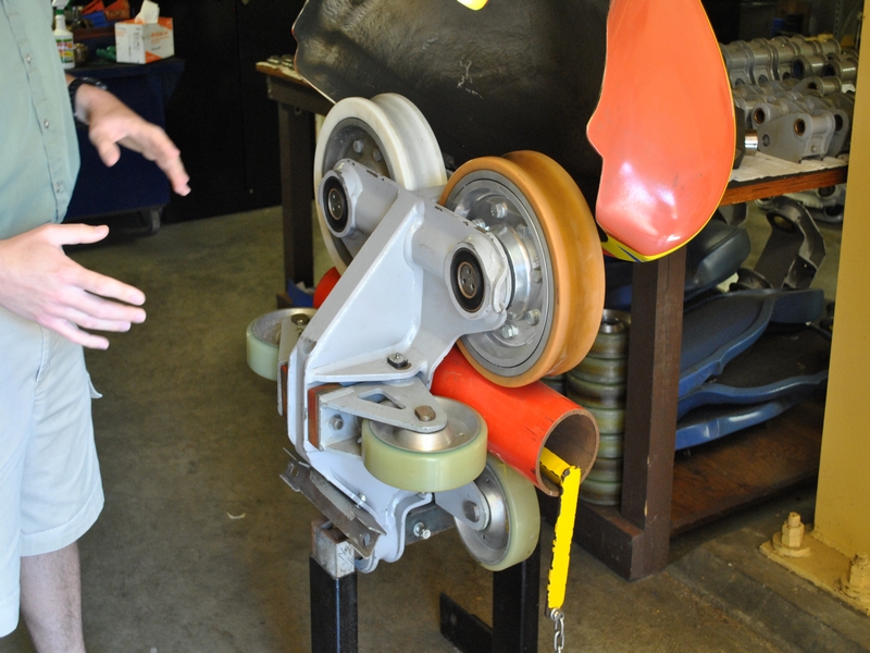
Here's a standard roller coaster wheel assembly, with six wheels.
Any 3? If the top two fail, the assembly drops from the rail, doesn't it? If the bottom two break off, the thing could derail in a negative g track part.
I would think that is only true if we consider that cars have more than one of these.
We are proud to say that Ben Katz, one of the leaders and designers of the project interned at Formlabs over the summer and used our printers to make a beautiful detailed model of the roller coaster.
I would have liked to see a loop combined with a gyroscopic chair, so no person is actually upside-down. It also seems like these are the sorts of things you are supposed to just build without university approval ala Real Genius.
MIT used to ignore this sort of thing and let it happen. After some students died roof and tunnel hacking, the attitude slowly changed, sadly. You can't do it without approval anymore.
I don't recall any deaths from roof and tunnel hacking. There are serious potential hazards. There is a case to be made for securing the roof of building 54 to deter suicides. But it appears that the much stronger security measures and much stiffer punishment for unauthorized roof and tunnel hacking since the '80s were not motivated by fatal events.
I did not suggest it was unsafe. I was suggesting they say to each new passenger "have you seen there's nothing to stop you going off the end?" just before they release the cart...
Yep. Been a big rush event for a while now. IIRC, Mark Feldmeier was a big part of the first incarnation. Such an awesome dorm. Always making stuff.
It was (is?) a big center of roof and tunnel hacking. One guy from my floor went out every night for a couple of years trying to collect all of Sophicles' sign-ins. And don't forget the Oddball Olympics. I remember the Master Lock picking event usually being won in less than 10 seconds.
You know Feldmeier? Awesome! I'm living in SH right now and he's always coming by and sparking interesting conversations. A month or two ago we held a showing of his re-soundtracked Metropolis – all techno music instead of the original score. What a great guy!
Feldmeier is my candidate for the most interesting man in the world. I remember stories about how one summer while interning at Apple, he voluntarily lived under a bridge. Then there was the year he lived in one of the 2W closets while I was there (2W, not the closet).
He's one of my favorite East Campus folks to tell stories about. Awesome guy.
Believe it or not, we have zero skateparks in Boston. There are plans to build a pretty extensive one however I haven't seen any real progress being made.
I was going to say, I hope someone got the chance to ride a skateboard on there. I would. We have a few parks outside of Boston. Nothing crazy, but better than nothing.
Ha totally agree. The loops and vicious turns are central to a roller coaster (and being tied to the track). Without those, sledding is way better cause you can get some serious airtime on the right hills and have some control over your direction too.
Overall a neat project for a large college team to work together on but the end product doesn't appear that functional/fun.
You definitely have the right perspective. If I put my kid's hat on, it definitely would be fun. Doing the simplest things with my nieces and nephews are extremely fun :)
While this is awesome work, I find it sad that those involved seem to have cheerfully acquiesced to the diktats of a safety- and image-obsessed administration.
Or perhaps their true attitude just wasn't appropriate for this blog post.
They had people manually pushing it back up the last two humps, and then they had a rope they hooked to the cart to pull it up the last hump.
Source: was one of the people pushing it back over the humps. Surprisingly a sketchy job - you have to really go for it to get it over the middle hump, and if you don't make it then you have to bail really quickly.
You'd either need to thread the rope through some kind of guides that would make it follow the contour of the track (which would almost certainly introduce vast friction losses in the force on the rope), or else the force on your rope if you just let it go freely through the air is going to be at vastly the wrong vector for efficient pulling of the sled as it goes over the secondary rises. I suspect you'd find that it becomes unfeasibly hard to pull the sled over the second rises via a rope that is pulled from the top of the primary tower.
It doesn't have enough momentum to fully go up the last 'slope' so it rolls back down with the momentum to get back to the starting position... I believe that's what i gathered from the end of the page.
By using such big bolts they actually made the structure less safe because they had to drill very large holes; those holes made the wood weaker than it otherwise would have been. I don't know who at MIT insisted that they use 1" bolts but that person had no business sticking their nose in.