This was how we did computer graphics before there were affordable (less than $50K) frame buffers in 1980.
In my 1975 MIT Digital Systems Lab my team constructed a hardware Game Of Life out of TTL gates. I designed the display as timed X-Y points on an oscilloscope. In those days a kilobyte of RAM still cost a hundred dollars, so the computer lab rationed the number of memory chips each team could use. I recall we stored the automata in a dual 64 x 64 bit frame buffer or two kilobytes overall.
The first generation computer graphics languages were vector-oriented to support either oscilloscopes or pen-plotters.
My first color frame buffer terminal was 512 x 512 x 8bits $30K AED in 1980. I think this costs than a dollar on a low-end cellphone now.
Ancient desktop is todays (or at least yesterdays) embedded. I guess this dates me but instead of taking the legacy Z80 embedded micro controller class a long time ago, I took the then new brand new 68hc11 class, although the Z80 guys got to use two DACs and a scope to display a cube on the scope as one of their labs. Now using a mhz class cpu to output a table at khz speeds isn't very impressive, so logically the next step in the lab was rotating the cube. I donno if they had to dream up their own trig or got a canned library. Maybe they canned the whole thing and just stored 30 or so frames of rotation data and switched which frame they displayed every tenth of a second or whatever. Donno didn't take the class but we got to see their work on lab day.
I would imagine whatever took a "sheet of paper" sized development board with dedicated hardware DACs and eproms around 1990 could be done as a single chip solution today, assuming you can find a single chip solution that actually has two on board DACs. Or up the challenge by synthesizing PWM signals and low pass filtering them, essentially a class D amplifier controlled by software.
Surprisingly or not, PWM circuits (a counter and binary comparator) are more common than DACs on today's microcontrollers. I blew up some somewhat expensive tweeters finding out that just because you can't hear the 31.275kHz PWM carrier doesn't mean the amplifier isn't amplifying it.
It is definitely plausible that they were rendering their spinning cube in real-time. A lot of people have written wolf3d-style raycasting engines for z80 (mostly z80-based TI graphing calculators, which are clocked between 6MHz and 15MHz. much faster than a TRS-80 to be fair). This guy even made a doom-style engine: http://benryves.com/journal/3739423 (see animated screenshot). The stuff the demoscene has done with z80 microcomputers can be even more impressive.
True, but I was concerned with it being a school lab, they were already demonstrating dual dacs, linked list data structure with semi-complicated data structure (well, OK, x and y values and maybe just a dumb lookup table) in assembly. Asking them to add a third aspect of trig might have been too much for one lab so maybe they canned the rotation and just had a very large data table animation rather than calculate on the fly.
My project for the demo day in 68hc11 class was the 68hc11 was a weirdo among microcontrollers for having an external memory bus, so I slapped a 32k sram onto it making it a 32K MC and made what amounts to a drum sampler, press this button to record a couple seconds off the onboard A/D and press this button to play it back using an offboard DAC. Now a days of course microcontrollers rarely expose their memory bus and you'd just buy a COTS MC with more memory on the chip. We only had one day to prep for demo day and asking the Z80 kids to do DACs, and a vector algo, and trig all in one day might have been asking too much.
Its been awhile, but I think the demo day theme was we all had to use at least one off chip DAC.
I saw a video titler which solved the problem of expensive memory by keeping the frame buffer compressed, and decompressing it at frame rate. I remember that composing the image was very slow (on a 4 MHz 68000). The compression algorithm was run length limited.
The product was the Vidstar-2000 from Video Data Systems in 1984.
Some early flight sims used a trick of rendering just before electron gun beam. You only needed a small amount of ram for a big screen, as long as you were able to keep up with the beam.
I'm old enough to remember when my college computer lab had an analog display for one of its systems...if I remember right, it was used for LaTeX applications and development, which during those days was still an interesting CS direction.
I used to be mesmerized by it..everything looked so clean and modern, much better then the crappy 80x25 "workstation" displays of the VAX's and PDP-11's.
This doesn't make sense in my head: I don't think vector displays were ever used for type setting, but I would love to be proven wrong. Do you have anymore information?
The 4014 had a series of commands for drawing both text and graphics
I was at the Florida Institute of Technology in 1985, and Lamport had just published the LaTex language and their was some interest in the department in getting a version of it running the the 4014...
I think someone hacked a version of it...but my aging memory fails me.
Vector displays don't usually handle text very well. They can draw perfect curves, but I don't think they could ever do the Bezier curves that fonts depend on.
Anyways, what you are referring to is in between vector and rasterized displays. Still very interesting. I should ask my dad about this (he worked for Textronix in the 70s).
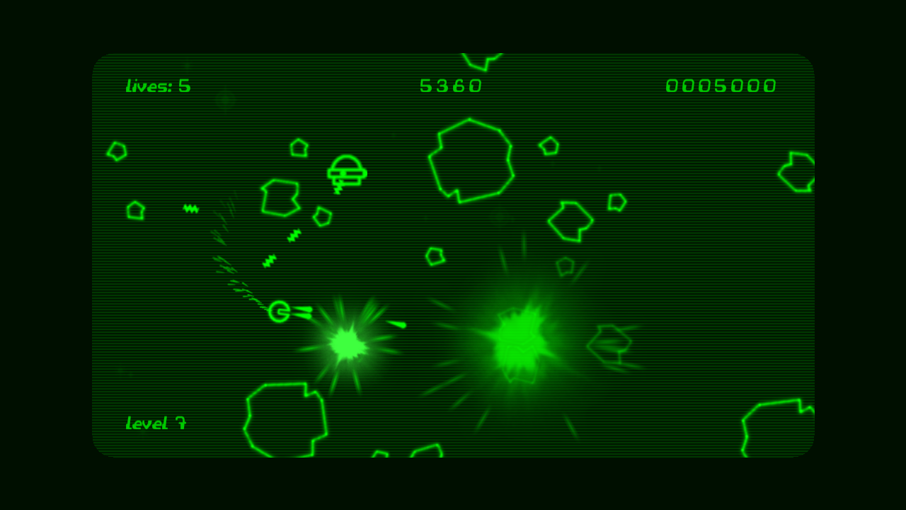
>This means the frequencies emitted are very high (5 samples per period is 19.2 kHz) and it seems the audio output is being low pass filtered resulting in silly wobbly lines.
That effect actually looks amazing. I'd totally play a game with that aesthetic.
Part of it would be done on a shader (mainly the visual portion, like the glowing and whatnot) but I think most of the effect would need to be done on the CPU.
You might be able to make it work with clever usage of geometry or tesselation shaders though, and maybe also transform feedback.
Honestly though, since the effect necessitates simple, low-poly geometry, doing the effect on the CPU shouldn't be too unreasonable, and would be where I would start.
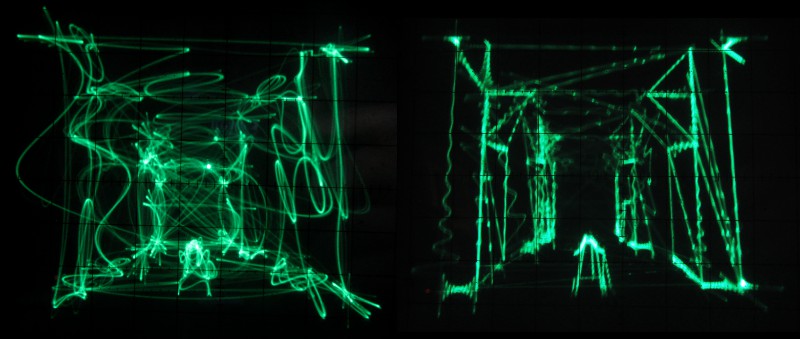
EDIT: Actually, now that I look closer, the one on the right here[0] could be done more reasonably in a shader, I was thinking closer to the one on the left (and how it actually looks in the video).
Always fascinated to see people use alternate input methods. I wonder if there is some possibility for steganographic applications with this? I.E., plug a soundcard into an oscilliscope, play a specially crafted .wav or equivalent file, and viola, secret message?
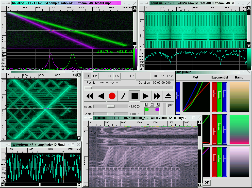
He used framework called Pure Data to build the sounds by additive synthesis (of pure sine waves). If you do that with some care (and you can pick the phases of the sine waves freely), you can build/explore/craft some pretty funky visuals quite easily, I imagine. It's the large scale composition, making it into a coherent whole that seems hardest to me (then, that is always my weak point when making music, I'll just keep practising :) )
Lots of older systems had vector rather than raster displays, from what I've heard of people who used them (too young myself) they were highly interactive - you could design movement and animation much more easily, and make the display very responsive. The major downside was not being able to do colour (easily), and not being able to cope with a lot of on-screen complexity (like the line count here not being much to shout about). Rasterised displays are a special case of vector, but with fixed bandwidth requirement.
Note that the corners between straight lines are brighter, it is because on Vectrex the way to control line brightness was to draw it over itself, also line crossings were brighter too.
Important to mention that many vector displays could NOT make curved lines though.
"After product rights reverted back to Smith Engineering, an attempt was made in the late 1980s to resurrect the Vectrex as a handheld. Unfortunately, the pending introduction of Nintendo's GameBoy in 1989 put a practical stop to such plans once and for all.
In the mid-1990s, Jay Smith generously placed the entire Vectrex product line into the public domain, opening up legal, not-for-profit distribution."
There was an early home gaming system called the Vectrex that was based entirely around this. They got around the lack of color with clear plastic screen overlays.
That looks really trippy. I think it would actually be a cool rendering mode to have in FPS games in general, on computer screens, particularly the cyber-/techno-punk kinds.
At first, I thought this was just going to be another person discovering that analog TV sets were really just oscilloscopes with predetermined sync; and then setting up a sync for the scope to turn it into a little TV...
How nice to be wrong! Hats off on this one. Nice hack indeed.
I wonder if the limit on lines was due to 20 kHz filters on the audio output. When the 24/96 audio sampling & perception discussion went by a few weeks ago I seem to recall some testing showing that even high sample rate sound hardware had low pass filters just above 20 kHz. This kind of issue should have been easy to spot in development and testing, though, so maybe just a limitation of the medium.
I've got an old hobbyist oscilloscope, it was my former boss and mentor's first scope. I really should hack up something with it along with some of these low cost cpu boards.
Given that this is a realtime 3d space squished into the bandwidth of audio, could a variation be done with a worn kinect to feed into headphones an audio waveform version of current surroundings that is capable of being translated by the brain back into 3d. As that sounds like a possible hack for giving some form of vision to the blind.
I'm not so sure. The brain's ability to process and interpret visual information and form an intricate understanding of 3d space seems to me a "hard-wired" process.
Sure, you could convert information encoding 3d space around a user and convey it to them in any number of methods, but that wouldn't leverage the brains very specialized mechanism for processing and interpreting visual information(which I rightly or wrongly conceptualize as a mix of hardware(some analogue of a video coprocessor for the brain) and software(the algorithms the brain uses to interpret the data).
The first link is interesting, it does say the saw signs of activity in the same brain region of a blind echo-locating person as a sighted person who is activity looking at something, but it is hardly a smoking gun.
Perhaps if you are defining "3d" information as something very primitive to the point of being "is there something directly in front of me", but nothing even as close as rich as even the quite crude 3d information being conveyed on the hacked oscilloscope outlined by the OP.
I do see technology eventually giving blind people some sort of "sight" back, but not for quite some time, perhaps after there is some sort of workable neural interface that currently lives solely in sci-fi.
Regarding the sound card, from the description it looks like the "crappy" sound card also employs a high-pass filter.
Is there a reason for it? What kind of circuit design in the DAC could cause low frequencies/significant distortion to require a high-pass at these frequency ranges?
Most PC sound cards employ so-called single-supply designs running their chips only between Ground and a single positive supply, e.g. 5V or 3.3V. So typically for a headphone output the amplifier will swing around 1.5 or 2.5V or so. To get rid of this offset, a capacitor is used. This capacitor, together with the headphones impedance, will function as a RC hipass.
What frequency ranges do you mean? Digitally, you can feed the output very-close-to 0 Hz signals. Without a high-pass filter, this essentially means outputting direct current. A lot of audio gear don't take kindly to DC signals various reasons; things like amplifiers or headphones.
You truly can play quake anywhere. I always liked ttyquake, which replaced the renderer with an ascii-art output. Actually quite playable if you set your font size small enough and your xterm large enough...
To bring this full circle, is anyone aware of a software oscilloscope for Windows / iOS that you could 'play' the wave file into to render his Quake demo via software?
Sounds neat, but a bit complicated. You have to take those edges and turn them into an efficient set of paths for the oscilloscope to trace, and you have to do it very fast.
An oscilloscope is a cathode ray tube that has an electron beam that can be moved around by applying varying voltages to its inputs. In this case it works as an XY plotter, i.e., you specify the X co-ordinate by the value of the voltage on one input and the Y co-ordinate by the value of the voltage on the other input.
You can display lines on the oscilloscope screen by giving a specially generated two channel audio as its input; one channel works as the X co-ordinate and the other one as the Y co-ordinate.
The game (Darkplaces which is a source port of Quake) renders a scene that has the lines to be drawn (triangles, in fact) on screen. The output of the game, i.e., the lines to be drawn on screen are sent to an audio synthesizer process(PortAudio). This process uses a sound card to create the audio. The output of the sound card is connected to the inputs of the oscilloscope which draws the lines on its screen.
So it's not the sound in the game that is producing the actual image. The output of the game is converted to an audio signal which when given as input to the oscilloscope creates the actual image.
This was posted earlier and set off the voting ring detector. I haven't looked closely, but that may have been a false positive. Since it's a good post and didn't get the attention it deserves, we won't treat this one as a duplicate.
The first generation computer graphics languages were vector-oriented to support either oscilloscopes or pen-plotters.
My first color frame buffer terminal was 512 x 512 x 8bits $30K AED in 1980. I think this costs than a dollar on a low-end cellphone now.