Oh neat, I just reproed it with a Pi 2 and a Canon Speedlight flash. I'll put my scope on the power lines and see what's happening when you flash the board. Sounds like from the thread one of the power ICs is photo sensitive.
edit: Wow yeah, here's a look at the 3.3V power line when you flash the board, it drops almost down to 0V and then wildly fluctuates for about 100 nanoseconds: http://imgur.com/hG86pRy
edit 2: Another interesting measurement, with the board _totally unplugged_ and flashing it you can see a big voltage spike on the 3.3V rail. Up to 6-7 volts or so for a few nanoseconds: http://imgur.com/td262QK
I guess not only can you learn about electronics but also Einstein's photoelectric effect with the Pi 2!
Alright I put the Pi 2 in a cardboard box and held the flash at the same spot (but the box obscures the light). It keeps running just fine and doesn't have the nasty spike. Definitely is something light related.
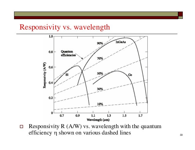
The responsivity of silicon (and other semiconductors) by wavelength is pretty well characterized[1]. Any data sheet for a silicon photodiode will include a similar plot, and as photodiodes are just diodes (granted, operated in reverse bias), regular diodes will have a similar response if light can get past the part package. Photodiode junction doping and geometry are optimized to make them useful as optical devices, but they're still VERY close to regular silicon diodes.
This property of diodes can be used in a fun way: LEDs emit light, but they can also be used as photodiodes[2]. It's easy with a microcontroller pin that can act as both a digital output and analog input. LEDs are of course not optimized for this use (small sensor area, the package may absorb useful light particularly in the UV, phosphor if present may get in the way), but they can be used as photodetectors. There's even an Arduino sketch[3].
Since the effect seems to be caused by a silicon component that isn't properly shielded from light, anything with a photon energy higher than the bandgap should do. The bandgap of silicon is 1.1eV, which means the effect should start in near-infrared.
The problem should happen with near-infrared, visible, and UV-light. Glass is transparent in the visible range, and depending on type, also in IR / UV, so glass won't work as a shield.
The easiest, reliable way to shield would be wrapping in aluminum foil (also helps against RF-interference).
Handy tip! Which - just tested - seems to work for me, at least with a couple of coats of black nail polish, and double-checked with a high-end Canon flash and a random green laser pointer. (Of course your mileage, and nail polish, may vary.)
I should change the hostname to nemi. ;)
There's another 'shiny' chip on the board too, next to the HDMI port, U8 I think, but it doesn't seem to give a damn what you do to that.
Compared to having to resolder all the Ethernet ports by hand, or USB power issues, this is a pretty minor errata! I presume the factory will pop a blob of epoxy on it for future runs, if they can't get this chip with a package on it.
I'm thinking of trying a more permanent fix with some Sugru[1] when my Pi 2 arrives. Their about says it's insulating and okay for electric repairs under 24 volts.
Not knowing what the IC is, one thought is that the blu-tac could be blocking light, or providing a wee bit of extra capacitance to tame a wicked electrical signal.
It's not a mains spike, but an EM discharge caused by the rapid voltage and current changes in the flash, that the parent comment is considering (IIUC).
Yes thankyou. This is what I'm getting at. The momentary power flow in a xenon flash is very large. A great big capacitor charges up and then discharges very rapidly to create the bright flash of light. There is also a high voltage exciter coil that fires to kick the xenon tube into conduction at the beginning of the flash cycle. Both of these could be very disruptive to nearby digital electronics.
I thought the original poster would be in a very good spot to help us determine if the effect if photoelectric or the result of EM because he's got everything set up. All he has to do is repeat the experiment while blocking the light from hitting the Pi.
I'll put it in a box and try in a little bit, sorry have to do a few things first. I'm 99% sure it's light dependent though, I had to aim the flash at the board and keep it somewhat close to get it to lock up (like 6" away or so).
The historical importance of the photoelectric effect is to demonstrate the relevance of the work function Ω. It works like this:
V ~ E_0 - Ω
where hf is the energy per photon and Ω is the work function of the target. If Ω > E_0, no voltage is produced. This provided the basis for Einstein's demonstration that energy is proportional to frequency (E_0 = hf), and won him the Nobel prize.
What does this have to do with xenon? Xenon lamps produce not only visible light, but also ultraviolet light, in fact, xenon lamps extend further into the UV than natural sunlight:
With this data we can determine that the work function of silicon (in the Raspberry Pi 2) is somewhere in the range of hc/(400 nm) < Ω < hc/(250 nm) or 3.1 eV < Ω < 5 eV. Using data from
The problem with your theory is that, as others have noted, the effect seems to happen with a red laser pointer as well.
To interfere with the electronics, the wavelength only has to as large as the band gap in silicon (as someone else has noted, around 1.1 eV). This means that IR light (and all visible light) can cause the interference too.
A strong enough light source will lift a lot of electrons from the valence band across the band gap into the conduction band, effectively turning a transistor into a conductor for the duration of the flash. Since the sensitive part seems to be related to the power supply, it's quite plausible that this leads to the voltage fluctuations on the power rail.
From The Devouring Fungus, Karla Jennings, 1990, chapter 10, The Monster Turns… and Falls to its Knees, p. 211:
Another legendary debacle triggered by light hit at a highly publicized affair thrown by IBM, ironic considering that IBM is the master of the seamless image. D. E. Rosenheim, who helped develop the IBM 701, the first mass-produced modern commercial computer, recalled the famous faux pas, which occurred when the company held a dedication ceremony for the 701’s installation at its New York headquarters. Top-level executives, the engineering team, and a gang of reporters crowded the ceremony room
“Things went pretty well at the dedication,” said Rosenheim, “until the photographers started taking pictures of the hardware. As soon as the flash bulbs went off, the whole system came down. Following a few tense moments on the part of the engineering crew, we realized with some consternation that the light from the flash bulbs was erasing the information in the CRT memory. Suffice it to say that shortly thereafter the doors to the CRT storage frame were made opaque to the offending wavelengths.”
Those who do not know their history are doomed to repeat it.
Note for the kids: Yes, that's right, it says CRT memory. That's the same Cathode Ray Tube as found in non-flat-panel TVs and monitors, except we're using it as a high speed storage device.
Ironically, the wikipedia page for Selectron tubes actually has more useful information on Williams tubes than it's article does... http://en.wikipedia.org/wiki/Selectron_tube
This reminds me of an old Finnish engineering legend from the early days of Nokia. The guys had just built an important prototype of some network equipment (early GSM base stations IIRC), which was going to be demonstrated for the press. All tests and previous demos had gone fine.
But as soon as the demo for the press started, the machine crashed. The management was upset. Later, the reason was found to be some old EPROM chips that are erased using UV light, and the photographers' cameras had strong flashes that went through the tapes covering the "window" on the chip. This caused the program memory to be corrupted when a photograph was taken.
Interesting that the Finnish version of this story is about Nokia, GSM base stations and EPROM memory. The version from 1990 from The Devouring Fungus which I quoted in a separate comment is about the IBM 701 and CRT memory.
One of the standard tests to gain an EMC Compliance Certificate is a spark discharge test.
Any experienced engineer will have a Spark Generator (Car Ignition coil, spark gap and short Dipole) to test to see if his latest project misbehaves when confronted with Impulse Interference.
As an EMC Investigator I would always carry a spark generator to demonstrate to newby engineers why EMC Compliance is so important.
I've seen a spark from 50ft away crash or reset a microprocessor system. Just the static discharge from walking on carpet is often enough.
I would tell you that pretending there isn't an implied distinction for everyone involved in a modicum of applied science is as counterproductive as arguing about the editor chosen for a coding tutorial.
Reminds me of old EPROMs. You can buy special "light sensitive" transistors, but they're really just ordinary transistors with a window in the case, since ordinary transistors are light-sensitive. You can even use an ordinary 1N4148 diode as a solar cell, it just doesn't generate much power.
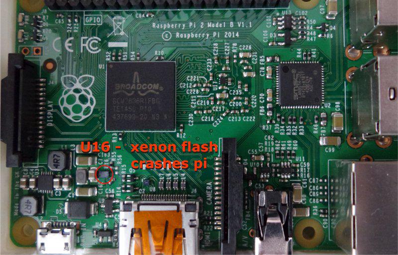
The fix is simple: apparently, you just have to cover U16, which controls the power supply.
There's nothing mysterious about this. Semiconductor gates are light-sensitive. There's usually carbon black in the plastic of plastic-packaged ICs to prevent interference from light. The opacity isn't perfect, though. For that you need ceramic or metal-encased ICs. Still, this is a rare enough problem that IC data sheets don't specify a maximum tolerated illumination level.
Try some laser pointers, especially towards the blue end of the spectrum where the photons have more energy. You may be able to trigger this effect by pointing at a specific IC.
its not missing it, its just a specific packaging type (flip chip). Its supposed to be used in products with full enclosure, or under a heatsink.
For example almost every single CPU and GPU nowadays uses some fcbga packaging (flip chip on ceramic/pcb carrier), but they are all hidden under heatsinks and often additional heat spreaders.
A xenon tube is not a spark gap, in terms of the early radio receiver 'spark gaps' which were a primitive tuned circuit used to then feed an antenna (it wasn't the spark itself that was used for the transmission).
Sparks produce a broadband radio signal, that decays strongly with increasing frequency. Very little is present in the Megahertz region, which is why lightening doesn't interfere with FM radio that much.
Radio frequencies below the gigahertz or high megahertz region will not interfere with the Pi as the wavelength of these is too long to effectively couple into the short circuit board traces.
Xenon flash tubes are not that noisy in terms of unwanted RF. Apart from anything else, you wouldn't be allowed to sell such radiating circuits in consumer equipment.
A xenon flash puts out an enormous amount of blackbody light (high in IR and NIR) in a very short time frame (as short as 100 ns). Plastics are not very IR blocking by themselves. Silicon has a band gap of 1.1 eV. Any photons above this energy will be absorbed across the gap, and interfere with the circuitry. Firing a xenon flash close to something will result in an instantaneous light flux many hundreds of times larger than direct sunlight.
So the circuit might be designed to be resistant to any ambient lighting situations, but not to being flashed.
As a commentator mentioned below, U16 is a switched mode power supply circuit. It's analogue, and switching quite fast. It doesn't take much for it to be disrupted & mess up a few cycles, possibly even then triggering some protection circuitry on the inputs of chips down the line.
Blue tack, being an insulator, will be almost totally transparent to radio frequencies.
I think the reason lightning doesn't perturb FM transmissions much is that lightning, being a source of additional energy in the receiver's passband, is an amplitude modulation interference source, whereas FM transmits its information by Frequency Modulation, which is nominally insensitive to AM EMI sources. Any amateur radio operator in the Midwest or Florida using AM on 144MHz will tell you that lightning for sure interferes with reception. With FM, not so much.
FM receivers have a limiter circuit, which cuts off any source of amplitude change from the original signal. I'm studying to become a ham right now, and this bit is fresh in my mind.
U16 appears to be in a WLCSP package (and others have noted that it is "shiny", which would also agree with the typical appearance of one), and WLCSPs do not have much of a package - they're essentially bare die that have had solder bumps attached to their top surface, and are mounted upside-down ("flip-chip" style) onto the PCB. It won't take much light intensity to cause photoelectric effects on a WLCSP.
Hi, you should have a look elsewhere in these comments where a HN user has reproduced it with his camera flash, but used a piece of cardboard to block the light and the Pi behaved normally.
Cardboard (and I'll wager the blue tack also) has negligible EM shielding effect, so I'd say that's pretty conclusive that it's a photoelectric problem.
A light flash is an EMP. Radio waves are light. They also, unless they are very short, pass easily through blue-tack. When they get that short they are basically becoming infra-red anyway. Then we have a wide range through the visible spectrum, up through UV, that blue-tack stops, until we start getting towards x-rays and blue-tack starts to become transparent again. This is caused by an electromagnetic pulse, but of one in or close to the visible spectrum, otherwise blue-tack would be useless.
edit :
The word light is commonly used as shorthand for variously the whole EM band, the near visible EM band and just the visible EM band.
If you are talking about the speed of light, it includes radio and gamma.
Discussing the colour of light on the other hand and you are referencing the visual system.
As soon as you start talking about visible light however, you are widening the definition of light again to include IR and UV and more, otherwise you would not need to clarify with the word visible.
edit 2 - darkmighty. I am not talking about the xenon bulb producing an RF EMP from the lamp flashing circuit, I am merely continuing the terminology used elsewhere in this thread, that a flash of visible light is also quite clearly a form of electromagnetic pulse.
edit 3 - foobarbecue. Radio as it gets shorter becomes microwave, then IR, then red, through green, past blue, goes to UV, then xrays, then gamma.
To the downvoters of the above comment: if it's technically incorrect, say so. I don't know if it is or not, but it's certainly not an offensively worded comment. When you downvote rather than respond, you are actually spreading ignorance. A downvote is an effort to mute. A half-muted incorrect technical comment will encourage far more ignorance than a properly corrected, visible one. Don't encourage ignorance.
True that, I always see downvotes without replies as nonsense. If they could argue something reasonable about the statement then they would post it, but since they don't do it then it's probably a downvote "just because I don't like the guy".
Ok I think the biggest misconception here is conflating the EMP with the Xenon lamp flash.
The EMP is generated by the lamp/flashing circuit, which is essentially acting like a small (but not atomic) dipole antenna excited by a pulse. Therefore it has a distinctive cut-off frequency, probably in the 10s of Mhz range but I'm not sure exactly (something like this: [1]). This pulse is picked up by wires that act as antenna, and you get RF interference.
The Xenon flash has also a distinct spectrum, but it's essentially contained in the visible light range (in a log-frequency spectral density plot) [2], which is what you want with a lamp! This emission is absorbed by the semiconductor material by exciting bandgaps: displacing electrons causing voltage spikes.
"When they get that short they are basically becoming infra-red anyway." You mean UV. You got your spectrum backwards.
You should probably just admit your error here -- it's light, not radio waves, causing the effect. Sure, they're part of a common spectrum, but your statement "radio waves are light" is obviously false. It's a bit like saying "red is blue".
Edit: I misread the above, lotsofmangos was talking about wavelengths coming from the radio site of the spectrum rather than light, so he didn't get it backwards. The rest of this post stands.
I have been saying all along that it is electromagnetic waves in the visible or near visible spectrum causing the effect, otherwise the bluetack would not work.
As to saying that radio is light, if calculating the propagation speed of a radio wave, you don't talk about its speed of radio, you talk about its speed of light. In many technical contexts, light is one of the default terms.
Also, there would be no need for the term 'visible light' if light could not be used to describe electromagnetic radiation outside the visible spectrum. Infra-red and ultra-violet are commonly thought of as light and you can even create lensing optics for radio waves and for x-rays.
Agree, not sure why you were downvoted. EMP is photons. They were already considering the non visible spectrum when talking UV. There's a real prejudice and ignorance regarding visible light versus the entire electromagnetic spectrum.
The new wave of single board computers really exposed me to the amount of failure that can happen at the electrical level. Growing up with large ATX boxes I'd never expect so many things to go wrong.
btw: anyone tried to light-freeze other devices (banana, orange, cubie, etc) ?
Question to HN: Does also the Raspberry Pi 1 B or B+ have this problem or is the Xenon flash problem specific to the Raspberry Pi 2 B? Is somebody willing to do this experiment/has done it?
All silicon is photosensitive to some extent. The power supply will be one of the few chips which is primarily "analog"; in particular it will have a bandgap voltage reference. That's exactly the sort of thing to be badly affected by a charge pulse from the flash. Glitching the power supply will then destabilise the digital logic it's powering.
The real question is how the light manages to get through the epoxy casing.
Yes, but if you were tasked with designing the epoxy that was going to be used in every IC everywhere, I would hope that you would go through the extra effort of adding dyes that were specifically opaque to UV and IR.
All chips are photosensitive and a xenon flash produces light from UV through to IR, so my guess would be that the plastic used for the casing on that chip is not entirely opaque to something at the top or bottom end of the visible spectrum, which is why most bright lights don't trigger it. At a bet, I'd say the top end, as otherwise radiant heaters would also probably kill them. Would be fun to play around with some filters and a flashgun and narrow down the frequency.
I think it's more likely to be the other way round, a lot of plastics are semi-transparent to IR, all block UV extremely strongly (as you start ionising electrons).
For instance, black PVC electrician's tape is entirely transparent to near-infrared, I use this to cover Xenon flashbulbs & still have an infrared-sensitive trigger fire from them.
That was my first guess as well, the only reason I discounted it was that then I would expect the effect to happen more often. I could be entirely wrong there however.
edit - ars, I'm out of replies, but thanks for that. I think you are probably right.
Not yet. Closed source binary blobs are necessary for booting and for accelerated video. In fact, it's the GPU that bootstraps the rest of the board when you first power it up.
There is work being done to write an open source driver for the GPU, with the blessing of the RPi Foundation and BSD-licensed code provided by Broadcom[1]. But I don't know if that will include the bootstrapping code, or how far along it is. Given that it is BSD licensed, it may not meet everyone's definition of "Free", but at least there is a good chance of having fully documented, source-available drivers in the future.
> Given that it is BSD licensed, it may not meet everyone's definition of "Free", but at least there is a good chance of having fully documented, source-available drivers in the future.
3-clause BSD (what's common these days) meets pretty much everyone's definition of Free:
That's because completely free means different things to different people. Does it include the firmware/bios? Are you only concerned with what runs on the CPU?
Original Raspberry Pi needs user to provide non-free firmware blobs on SD card to even boot the CPU. That's pretty non-free in any meaning I can imagine.
It seems like it's still the case with Raspberry Pi 2.
The only difference between that an a PC is that the PC stores the firmware blob in a ROM chip while the Pi stores it on the SD card. Both require it to boot.
All of the badly-designed ones and none of the well-designed ones :) Often you'll see audio equipment with LED-biased voltage amps where the LEDs have some opaque glop slathered on them so they don't make popping sounds under bright lights, and to a lesser extent so multiple channels inside the same box are optically coupled, which is a concern. LEDs are photovoltaic like any other semiconductor but for obvious reasons they are not sold in opaque packages.
You could probably find devices that are disturbed by loud sounds and physical shock, because ceramic capacitors are microphonic.
RF stands for radio frequency, and defines a band of electromagnetic radiation, popularly known as light, that is on a continuum of frequencies that above RF pass through visible light and on towards gamma rays.
In simple terms, whenever something possessing charge moves it generates an electromagnetic wave associated with the motion and at right angles to it. Visible light is generated by motions of electrons at an atomic scale, radio frequency is motion of electrons at the scale of antennas, but they both generate electromagnetic waves quantized as photons.
edit - darkmighty. Electromagnetic radiation at radio frequencies is popularly known as light in contexts such as speed, but not in contexts such as colour.
RF refers to specific frequencies of radiation, which are not popularly known as light at all. Radio is usually in the MHz range to a few GHz (10^6-10^9 Hz). Light starts a hundreds of Terahertz (10^14 Hz). The behavior is qualitatively different at usual scales due to quantum mechanical behavior (light is difficult to emit/absorb coherently -- it's more particle-like) at high frequencies.
A photon striking a semiconductor will probably displace an electron if given an adequate bandgap, creating a voltage spike (which is nonlinear -- i.e. the problem isn't a propagating terahertz wave obviously). An incident radio wave will cause voltage spikes through coherent induction in the wires (i.e. they act as an usual antenna).
Even if there is no fundamental reason to believe that quantum theory would make a distinction between "microwave photons" and "optical photons", this demonstration puts this equivalence across a huge frequency range on a firm experimental footing. Moreover, the lower frequency of the microwave photons enabled a more complete characterization of the effect than has been able so far with optical photons, opening up new possibilities to characterize radiation sources. Finally, the new experiment highlights how quantum optical effects can be exploited in experiments with microwave sources, which may lead to practical applications of "microwave optics".
Explanation:
Camera's have capacitors that charge up in order for the flash to happen. They are usually quite powerful. Now during the discharge (aka flash) what you have is very high energy electrons flowing across the wire creating aa magnetic field, coupled with the electric field of the electron you get a mild EMP.
And if it is light sensitivity then it should be tested with a bright continuous light
edit: Wow yeah, here's a look at the 3.3V power line when you flash the board, it drops almost down to 0V and then wildly fluctuates for about 100 nanoseconds: http://imgur.com/hG86pRy
edit 2: Another interesting measurement, with the board _totally unplugged_ and flashing it you can see a big voltage spike on the 3.3V rail. Up to 6-7 volts or so for a few nanoseconds: http://imgur.com/td262QK
I guess not only can you learn about electronics but also Einstein's photoelectric effect with the Pi 2!